Products
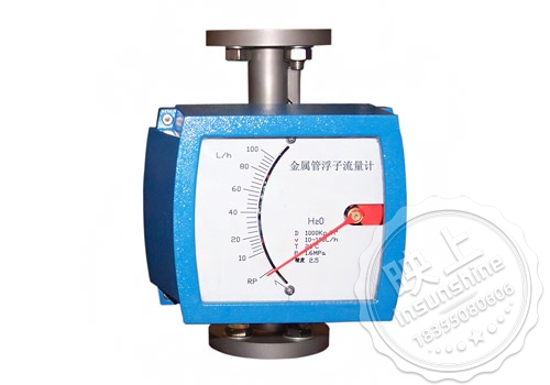
CH-LZ series metal tube rotor flowmeter is industrial automation process control commonly used in a flow measurement instrument, it has a small pressure loss, large detection range (range ratio of 10:1), easy to use and so on, it can be used to measure the flow of liquids, gases, and steam flow, especially suitable for low-flow rate of small flow media flow measurement. SC-LZ series metal tube float flowmeter has on-site display type and intelligent remote transmission type, with pointer display, instantaneous flow, cumulative flow, liquid crystal display, upper and lower limits of the alarm output, the cumulative pulse output, the standard two-wire 4-20mA current output and so on a variety of forms, for the user to provide a very broad choice of space. In addition, the meter adopts high-quality MCU microprocessor system, which ensures the excellent performance of the flowmeter in various applications.
Over the years, the metal tube float flowmeter's various excellent performance and reliability, as well as better performance-price ratio widely favored by the petrochemical, iron and steel, electric power, metallurgy, light industry and other industries. Welcome to inquire the price of metal tube float flowmeter.
CH-LZ series metal tube float flowmeter structure principle
1、Structure
CH-LZ series metal tube float flowmeter is mainly composed of three major components
a, indicator (intelligent indicator, in situ indicator)
b, float
c, conical measuring chamber
| Measurement range | water:2.5~100000L/h |
| Air:0.07~3000m³/h | |
| range ratio | 10:1(DN≤100mm) |
| 5:1 (DN≤100mm) | |
| Accuracy Class | Standard class 1.5, special order up to class 1.0 |
| work pressure | DN15、DN25、DN40、DN50~4.0MPa |
| DN80、DN100、DN150~1.6MPa | |
| Medium temperature | normal type:-40℃~100℃ |
| High Temperature:-80℃~250℃ | |
| Lined with F46 fluorine plastic:-40℃~+80℃,内衬PFTE-40℃~+120℃ | |
| environmental temperature | pointer:-40℃~+65℃ |
| intelligent:-25℃~+65℃ | |
| connection method | Flange connection, threaded connection, clamp connection |
| electrical interface | M20×1.5(Special requirements can be made) |
| protection class | IP65 |
| Explosion-proof grade | Intrinsically safe: ExibIICT4 (with LB987S safety grid) Explosion-proof: ExdIIBT4 |
| Viscosity of the medium | DN15≤5Mpa.s DN25~150≤5Mpa.s |
| Measuring tube material | stainless steel 316 stainless steel, 304 or 316L stainless steel lined with FTFE or F46 |
| Float Material | 304 or 316 (stainless steel); FTFE or F46 |
III. Selection reference table
| Pipe caliber | structural form | Catch material | add-on structure | |||
| A | B | Medium flow direction | C | D | ||
| DN15 | Y10 | in-and-out | RRO | 0Cr18Ni12Mo2Ti | F | Anti-corrosion type |
| DN25 | Y20 | barge in and out | RR1 | 1Cr18Ni9Ti | T | Jacketed |
| DN50 | Y30 | ipsilateral access | RP | (PTFE) | Z | Damping type |
| DN80 | Y40 | opposing sides entering and leaving | Ti | (Titanium alloy) | G | High Temperature |
| DN100 | Y50 | Bottom side access | RL | 316L | Y | high voltage type |
| DN125 |
|
|
|
|
B | explosion proof |
| DN150 |
|
|
|
|
|
|
IV. Flow ranges
| Corrosion-resistant diameter | Ordinary diameter | Measurement range | ***Pressure loss | ||
| DN(mm) | DN(mm) | air20℃ m3/h | water(20℃)(L/h) | air(KPa) | water(KPa) |
| 15 | 15 | 0.05-0.5 | 1.6-16 | 7 | 6.4 |
| 0.07-0.7 | 2.5-25 | 7.1 | 6.5 | ||
| 0.11-1.1 | 4.0-40 | 7.2 | 6.5 | ||
| 0.18-1.8 | 6.0-60 | 7.3 | 6.6 | ||
| 0.28-2.8 | 10-100 | 7.5 | 6.6 | ||
| 0.40-4.0 | 16-160 | 8 | 6.8 | ||
| 0.70-7.0 | 25-250 | 10.8 | 7.2 | ||
| 1.00-10 | 40-400 | 10 | 8.6 | ||
| 1.60-16 | 60-600 | 14 | 11.1 | ||
| 25 |
|
80-800 |
|
14 | |
| 25 | 3.00-30 | 100-1000 | 7.7 | 7 | |
| 4.50-45 | 160-1600 | 8.8 | 8 | ||
| 7.00-70 | 250-2500 | 12 | 10.8 | ||
| 11-110 | 400-4000 | 19 | 15.8 | ||
| 50 |
|
500-5000 |
|
16.2 | |
| 50 | 18-180 | 600-6000 | 8.6 | 8.1 | |
| 25-250 | 1000-10000 | 10.4 | 11 | ||
| 80 | 40-400 | 1600-16000 | 12.6 | 17 | |
| 80 | 50-500 | 2000-20000 | 15.5 | 6.3 | |
| 100 | 75-750 | 2500-25000 | 17.2 | 8.1 | |
| 100 | 100-1000 | 4000-40000 |
|
9.5 | |
| 125 | 160-1600 | 6000-60000 |
|
10 | |
| 125 | 250-2500 | 8000-80000 |
|
16 | |
| 150 |
|
10000-100000 |
|
20 | |
|
|
300-3000 | 12-120m3/h |
|
20 | |
|
|
400-4000 | 15-150m3/h |
|
25 | |
V. External Dimensions
| Caliber/Pressure | Size (mm) | Φd3 | Φk | Φd2 | b | f | L | h |
| 15/4.0 | 95 | 45 | 65 | 4xΦ14 | 16 | 2 | 250 | 85 |
| 25/4.0 | 115 | 68 | 85 | 4xΦ14 | 18 | 2 | 250 | 85 |
| 50/4.0 | 165 | 102 | 125 | 4xΦ18 | 20 | 3 | 250 | 85 |
| 80/1.6 | 200 | 138 | 160 | 8xΦ18 | 20 | 3 | 250 | 85 |
| 100/1.6 | 220 | 162 | 180 | 8xΦ18 | 20 | 3 | 250 | 85 |
| 125/1.6 | 250 | 188 | 210 | 8xΦ18 | 22 | 3 | 400 | 85 |
| 150/1.6 | 285 | 218 | 240 | 8xΦ22 | 22 | 3 | 400 | 85 |
1. The metal tube float flowmeter must be installed vertically on a vibration free pipeline. The fluid flows through the flowmeter from bottom to top, and the verticality is better than 2 °. When installed horizontally, the horizontal angle is better than 2 °;
2. For the convenience of maintenance, replacement of flow meters, and cleaning of measuring pipelines, metal tube float flow meters installed on process pipelines should be equipped with bypass pipelines and bypass valves;
3. The inlet of the metal tube float flowmeter should have a straight pipe section of at least 5 times the diameter of the pipe, and the outlet should have a straight pipe section of 250mm;
4. If the medium contains ferromagnetic substances, a magnetic filter should be installed; If the medium contains solid impurities, it should be considered to install a filter between the valve and the straight pipe section;
5. When used for gas measurement, it should be ensured that the pipeline pressure is not less than 5 times the pressure loss of the flowmeter to ensure stable operation of the float;
6. In order to avoid deformation of the flow meter caused by the pipeline, the flange of the process pipeline must be coaxial and parallel to the flange of the flow meter. The pipeline support should be used to avoid pipeline vibration and reduce the axial load of the flow meter. The control valve in the measurement system should be installed downstream of the flow meter:
7. When measuring gas, if the gas is directly discharged into the atmosphere at the outlet of the flowmeter, a valve should be installed at the outlet of the instrument, otherwise a pressure drop will occur at the float, causing data distortion.
8. When installing instruments with PTFE lining, do not tighten the flange nuts asymmetrically at will to avoid deformation of the PTEF lining;
9. Used for flow measurement of small caliber and low velocity media; Reliable work, minimal maintenance, and long lifespan; The requirements for straight pipe sections are not high; A wider flow ratio of 10:1; Dual row large LCD display, optional on-site instantaneous/cumulative flow display, with backlight single axis sensitive indication; Non contact magnetic coupling transmission.