Product Introduction
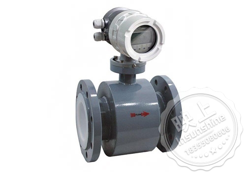
The domestic sewage flow meter, also known as the electromagnetic flow meter, is a high-precision, highly reliable, and long service life flow instrument. Therefore, we are very meticulous in every aspect of the design of product structure, material selection, process formulation, production assembly, and factory testing. We have also independently designed a set of advanced production equipment and flow calibration devices dedicated to electromagnetic flow meters in China, which can effectively ensure the long-term high quality of products in both software and hardware.
The electromagnetic flowmeter is specially designed with a backlit wide temperature Chinese LCD display, which is fully functional, practical, intuitive, and easy to operate, reducing the inconvenience caused by the English menu of other electromagnetic flowmeters. In addition, we have designed a 4-6 multi electrode structure to further ensure measurement accuracy and eliminate the need for grounding rings at all times, reducing the size of the instrument and the trouble of installation and maintenance.
Performance characteristics of intelligent electromagnetic flowmeter:
The measurement accuracy is not affected by changes in fluid density, viscosity, temperature, pressure, and conductivity. The sensor's induced voltage signal is linearly related to the average flow rate, resulting in high measurement accuracy.
There is no obstruction in the measuring pipeline, so there is no additional pressure loss; There are no movable parts inside the measuring pipeline, so the sensor has an extremely long lifespan.
Due to the fact that the induced voltage signal is formed in the entire space filled with a magnetic field and is the average value on the surface of the pipeline, the straight pipe section required for the sensor is relatively short, with a length of 5 times the diameter of the pipeline.
The sensor part only has the inner lining and electrodes in contact with the measured liquid. As long as the electrode and inner lining materials are selected reasonably, they can be corrosion-resistant and wear-resistant.
The LDE converter adopts international * * * new * * advanced microcontroller (MCU) and surface mount technology (SMT), with reliable performance, high accuracy, low power consumption, stable zero point, and convenient parameter setting. Click on the Chinese display LCD to show cumulative flow, instantaneous flow, flow rate, flow percentage, etc.
A bidirectional measurement system that can measure both forward and reverse flow rates. Using special production processes and high-quality materials to ensure stable product performance over a long period of time
Comparison Table of Flow Caliber
| Caliber mm | Flow range m³/h | Caliber mm | Flow range m³/h |
| DN10 | 0.16~2.5 | DN400 | 250~4000 |
| DN15 | 0.4~6 | DN500 | 400~6000 |
| DN20 | 0.6~12 | DN600 | 600~10000 |
| DN25 | 1.0~16 | DN700 | 800~12000 |
| DN32 | 1.6~25 | DN800 | 1000~16000 |
| DN40 | 2.5~40 | DN900 | 1200~20000 |
| DN50 | 4.0~60 | DN1000 | 1600~25000 |
| DN65 | 6.0~120 | DN1200 | 2500~30000 |
| DN80 | 10~160 | DN1400 | 3000~50000 |
| DN100 | 16~250 | DN1600 | 3000~60000 |
| DN125 | 25~400 | DN1800 | 5000~60000 |
| DN150 | 40~600 | DN2000 | 6000~100000 |
| DN200 | 60~1000 | DN2200 | 1367.78~136778.4 |
| DN250 | 100~1600 | DN2400 | 1627.78~162777.6 |
| DN300 | 160~2500 | DN2600 | 1910.38~191037.6 |
| DN350 | 200~3000 | DN2800 | 2306.56 ~ 236062.8 |
Product Selection
| model number | caliber |
|
||||||
| CH-LEL | 10~2600 | |||||||
|
|
|
nicknames | Installation form |
|
||||
| Y | all-in-one | |||||||
| F | split | |||||||
|
|
nicknames | Converter Model | ||||||
| ZA | orbicular | |||||||
| ZB | Square (split only) | |||||||
|
|
nicknames | Type of power supply | ||||||
| AC | 220V AC 50Hz(90~245V AC 50Hz) | |||||||
| DC | 24V DC (20~36V DC) | |||||||
| LD | Lithium battery powered (without signal output) | |||||||
|
|
nicknames |
|
|
|
||||
|
|
I |
|
|
|
||||
|
|
f |
|
|
|
||||
|
|
Rs |
|
|
|
||||
|
|
H |
|
|
|
||||
|
|
C |
|
|
|
||||
|
|
|
Medium temperature | ||||||
| ≤65℃ | ||||||||
| ≤120℃ | ||||||||
| ≤180℃(Split type only) | ||||||||
| nicknames | Lining Material | |||||||
| NE | neoprene(≤65℃) | |||||||
| PVC | (≤70℃) | |||||||
| PU | (≤80℃) | |||||||
| PTFE | (≤180℃) | |||||||
|
|
nicknames | Electrode Material | ||||||
| 316L | stainless steels | |||||||
| HC |
|
|||||||
| Ti |
|
|||||||
| Ta |
|
|||||||
| Pt |
|
|||||||
| Warm tips: flowmeter selection must, media, caliber (flow range), electrode material, lining material, installation requirements | ||||||||
| Electromagnetic flow meter | ||
| vantage | drawbacks | |
| 1 | There are no moving parts and no throttling parts in the measuring tube to impede the flow of fluid, which does not cause any additional pressure loss when the fluid passes through the meter. | It can only measure the liquid flow of conductive media, not the flow of non-conductive media |
| 2 | Electromagnetic flow meters can be used to measure the flow of other electrically conductive liquids after calibration with water only. | Cannot be used to measure gases, vapors, or liquids containing large quantities of gases. |
| 3 | Their range ratios can be up to 20:1, and some even up to 100:1 range ratios. | The medium in the pipe must be full, and cannot be measured out of a full pipe. |
| 4 | No mechanical inertia, sensitive response, can measure instantaneous pulsating flow, positive and negative direction of flow | Can only be measured above DN10 pipe, not applicable to small diameter |
| 5 | Measure the flow of corrosive media, spoiled media and suspended liquid-solid two-phase flow. | Cannot measure hydrofluoric acid media |
1, should be installed in the horizontal pipeline lower and vertically upward, avoid installation in the pipeline *** point and vertical downward;
2、It should be installed at the rising place on the pipeline;
3, in the open discharge pipeline installation, should be installed in the lower part of the pipeline;
4、If the pipeline drop is more than 5m, an exhaust valve should be installed downstream of the sensor;
5, should be installed downstream of the sensor control valves and shut-off valves, and should not be installed in the sensor upstream;
6, the sensor *** can not be installed in the pump inlet and outlet, should be installed in the pump outlet.