Products
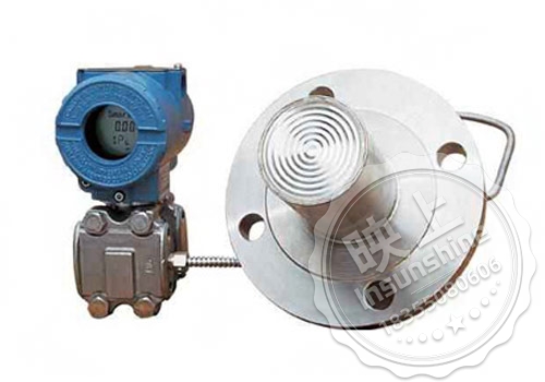
The sealing diaphragm of the diaphragm-sealed remote pressure transmitter is used to prevent the medium in the pipeline from entering directly into the pressure sensor assembly in the differential pressure transmitter, which is connected to the transmitter by a capillary tube filled with fluid.SC438W, SC438N (the same as the EJA438W, EJA438N) diaphragm-sealed pressure transmitters are used for the measurement of the flow of liquids, gases and vapors, level, density and differential pressure of liquids, gases and vapors, and then output a 4~20mA DC signal corresponding to the measured differential pressure. It can also be used to communicate with the hand operated device for remote setting and monitoring.
More information of Diaphragm Sealed Pressure Transmitter:
I. Standard technical specifications
1.1 Communication line conditions
Power supply voltage: 16.4~42V DC (16.4~30V DC)
Communication distance: 2km (using CEV cable)
Load capacitance: 0.22µF or less
Load inductance: 3.3mH or less
Distance from power supply line: 15cm or more
Input impedance of the receiving instrument connected to the receiving resistor is 10kΩ or more at 2.4kHz.
1.2 Ambient temperature
General type diaphragm sealed pressure transmitter: -40~85℃ (-40~185?F)
Diaphragm Sealed Pressure Transmitter with Digital Gauge Head: -30~80℃ (-22~176?F)
1.3 Working pressure (rated working pressure of flange: 2.7kPa abs or 20mmHg abs)
1.4 Effect of power supply voltage variation: ±0.005%/V (21.6 to 32V DC, 350Ω)
1.5 Installation: Transmitter: 2inch pipe mounting; diaphragm seal: flange mounting.
1.6 Mounting flange specifications: ANSI specifications for the flange and gasket contact side, serrated processing (according to ANSI B16.5).
1.7 Waterproof structure: JIS C0920 immersion-proof type (equivalent to IEC IP67 and NEMA 4X)
1.8 Transmitter material: flange: JIS SUS14A; flange bolts: see “Model and specification code table”.
1.9 Diaphragm seal material: capillary tube: JIS SUS316; protection tube: JIS SUS304; PVC shielding (PVC *** use temperature: 100 ℃)
1.10 Damping time constant: the amplifier assembly and the diaphragm box with diaphragm seals formed by the sum of the time constant value (amplifier formed by the time constant: 0.2 to 64 seconds, can be set in 9 segments; when the capillary tube is 3m long and the injection of liquid code A, the value is obtained at normal temperature).
II. Model and specification code list
2.2 Flat / Convex Diaphragm Sealed Remote Pressure Transmitter
|
Model No. |
Specification Code |
Explanation |
ex-factory price |
note |
|||||||||||
|
|
|
Flat Diaphragm Type Diaphragm Sealed Pressure Transmitter |
|
|
|||||||||||
|
output signal |
E |
4~20mA, HART protocol digital communication 4~20mA
|
|
|
|||||||||||
|
Measurement range (Membrane box)
|
A |
0.06~3Mpa |
|
|
|||||||||||
|
Liquid-accepting part material |
|
cassette |
plumbing |
other than |
|
|
|||||||||
|
S |
JIS SUS316 |
JIS SUS316 |
JIS SUS316 |
||||||||||||
|
Flange Specifications |
J1 |
JIS10K |
|
|
|||||||||||
|
Diaphragm projection length
(X2)
|
2 |
X2=50mm |
|
|
|||||||||||
|
Flange Size/Material |
G |
3-inch(80mm,DN80)/JIS S25C |
|
|
|||||||||||
|
Flange Bolt Material |
A |
JIS SCM435 |
|
|
|||||||||||
|
Injection Fluid
(usually B)
|
|
|
Catch temperature ℃ |
Ambient temperature ℃ |
|
|
|||||||||
|
A |
General type (silicone oil) |
-10~250 |
-10~60 |
||||||||||||
|
B |
General type (silicone oil) |
-30~180 |
-15~60 |
||||||||||||
|
Capillary length (m) |
□□ |
Prescribed capillary lengths from 1 to 5 m, indicated by □□ (e.g., 2 m) |
|
|
|||||||||||
|
mounting |
9 |
Horizontal piping connection, left high pressure |
|
|
|||||||||||
|
electrical interface |
5 |
G½ female thread, 2 ports with blind plugs |
|
|
|||||||||||
|
Display Header |
D |
Digital Meter Heads
Digital display meter with range setting switch
(without meter head)
|
|
|
|||||||||||
|
2-inch pipe mounting bracket |
D |
JIS SECC Flat Bracket
JIS SECC Flat Bracket
No
|
|
|
|||||||||||
|
Additional Selection Codes |
|||||||||||||||
|
|
/□ Attachment |
|
|
||||||||||||
III. Dimensions
3. Diaphragm Sealed Pressure Transmitter with Convex Membrane Type
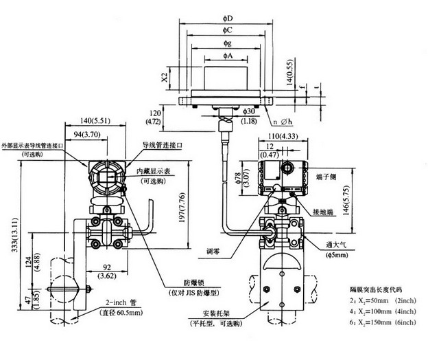
Flange Size: 4-inch (100mm, DN100))
|
Flange Specifications |
ØD |
ØC |
Øg |
Ød |
t |
f * |
n |
Øh |
|
JIS 10K |
210(8.72) |
175(6.89) |
155 |
96 |
18(0.71) |
0 |
8 |
19(0.75) |
|
JIS 20K |
225(8.86) |
185(7.28) |
24(0.94) |
0 |
8 |
23(0.91) |
||
|
ANSI 150 |
228.6(9.00) |
190.5(7.50) |
23.9(0.94) |
1.6(0.06) |
8 |
19.1(0.75) |
||
|
ANSI 300 |
254(10.00) |
200.2(7.88) |
31.8(1.25) |
1.6(0.06) |
8 |
22.4(0.88) |
||
|
JPI 150 |
229(9.02) |
190.5(7.50) |
24(0.94) |
1.6(0.06) |
8 |
19(0.75) |
||
|
JPI 300 |
254(10.00) |
200.2(7.88) |
32(1.26) |
1.6(0.06) |
8 |
22(0.87) |
||
|
DIN PN10/16 |
220(8.66) |
180(7.09) |
20(0.79) |
0 |
8 |
18(0.71) |
||
|
DIN PN25/40 |
235(9.25) |
190(7.48) |
24(0.94) |
0 |
8 |
22(0.87) |
||
|
GB PN10/16 |
220(8.66) |
180(7.09) |
22(0.87) |
3(0.12) |
8 |
18(0.71) |
||
|
GB PN25/40 |
235(9.25) |
190(7.48) |
26(1.02) |
3(0.12) |
8 |
22(0.87) |
||
|
GB PN100 |
275(10.83) |
216(8.50) |
38.5(1.51) |
7(0.28) |
8 |
26(1.02) |
Flange Size: 3-inch (80mm, DN80))
|
Flange Specifications |
ØD |
ØC |
Øg |
Ød |
t |
f * |
n |
Øh |
|
JIS 10K |
185(7.28) |
150(5.91) |
130 |
71 |
18(0.71) |
0 |
8 |
19(0.75) |
|
JIS 20K |
200(7.87) |
160(6.30) |
22(0.87) |
0 |
8 |
23(0.91) |
||
|
ANSI 150 |
190.5(7.5) |
152.4(6) |
23.9(0.94) |
1.6(0.06) |
4 |
19.1(0.75) |
||
|
ANSI 300 |
209.6(8.25) |
168.1(6.62) |
28.5(1.12) |
1.6(0.06) |
8 |
22.4(0.88) |
||
|
JPI 150 |
190(7.48) |
152.4(6) |
24(0.94) |
1.6(0.06) |
4 |
19(0.75) |
||
|
JPI 300 |
210(8.27) |
168.1(6.62) |
28.5(1.12) |
1.6(0.06) |
8 |
22(0.87) |
||
|
DIN PN10/16 |
200(7.88) |
160(6.30) |
20(0.79) |
0 |
8 |
18(0.71) |
||
|
DIN PN25/40 |
200(7.88) |
160(6.30) |
24(0.94) |
0 |
8 |
18(0.71) |
||
|
GB PN10/16 |
200(7.88) |
160(6.30) |
20(0.79) |
3(0.12) |
8 |
18(0.71) |
||
|
GB PN25/40 |
200(7.88) |
160(6.30) |
24(0.94) |
3(0.12) |
8 |
18(0.71) |
||
|
GB PN100 |
210(8.27) |
168.5(6.63) |
32(1.10) |
7(0.28) |
8 |
18(0.71) |