Products
Monocrystalline silicon pressure sensor principle of operation
As shown in Figure 1, monocrystalline silicon sensor sensitive element is the P-type impurities diffusion to the N-type silicon wafer, the formation of a very thin conductive P-type layer, welded leads into the “monocrystalline silicon strain gauges”, its electrical properties are made into a fully dynamic piezoresistive effect of the Whisden bridge. The piezoresistive effect of the Whisden bridge and the elastic element (i.e., its N-type silicon substrate) combined together. Medium pressure is transmitted to the positive side of the silicon diaphragm through the sealed silicone oil, and the medium acting on the negative side of the cavity to form a pressure difference, the result of their joint action so that the diaphragm of the side of the compression, the other side of the tension, the pressure difference to make the bridge imbalance, and the output of a signal corresponding to the pressure change. The output signal of the bridge is processed by the circuit, which produces a 4-20mA standard signal output that is linearly related to the pressure change.
For gauge pressure sensors, the negative side of the chamber is usually open to the atmosphere, with atmospheric pressure as the reference pressure; for adiabatic pressure sensors, the negative side of the chamber is usually a vacuum chamber, with a vacuum as the reference pressure; for differential pressure sensors, the pressure-conducting medium on the negative side of the chamber is usually the same as on the positive side of the chamber, e.g., silicone oil, fluorine oil, vegetable oil and so on.
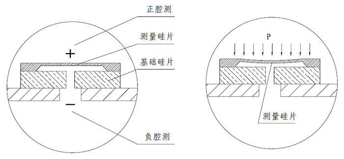
Fig. 1 Silicon sensor structure Fig. 2 Schematic diagram of diaphragm pressure
As shown in Figure 2, under the action of the pressure difference between the positive and negative chambers, the measuring silicon diaphragm (i.e., the elastic element) is caused to deform and bend, and the bending can be fully reset when the pressure difference P is less than the required stress ratio limit σp of the measuring silicon diaphragm; when the pressure difference P exceeds the required stress ratio limit σp of the measuring silicon diaphragm, the yield stage of the material will be reached, or even reach the stage of reinforcement, and at this point the measuring silicon diaphragm can not be restored to its original position after the withdrawal of the pressure difference. When the differential pressure P reaches or exceeds the ZUI high stress σb that the measuring silicon diaphragm can withstand, the measuring silicon diaphragm ruptures, which directly leads to sensor damage. Therefore, the measurement accuracy and lifetime of the sensor can be effectively protected by preventing or weakening the direct transfer of the external overload differential pressure P to the measurement silicon diaphragm. This leads to the issue of overload protection design for single crystal silicon chips.
As shown in Figure 3, in order to overcome the defects of monocrystalline silicon wafers with insufficient overload resistance, a differential pressure sensor with unidirectional pressure overload protection is equipped. The unidirectional pressure overload protection differential pressure sensor can not only measure the field conditions in the rated pressure range of the differential pressure value, but also in the event of unidirectional pressure overload can be effective self-protection, to avoid the damage caused by unidirectional pressure overload of silicon differential pressure sensing.
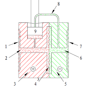
Fig. 3 Schematic structure of differential pressure sensor with overload protection
As shown in Figure 4 and Figure 5, when there is more than the differential pressure measurement silicon diaphragm allows the emergence of the operating range of the differential pressure, the center of the isolation of the mobile diaphragm to move to the low-pressure side, and make the high-pressure side of the outside world of the isolation of the diaphragm and the chamber interior wall overlap, thus making the high-pressure side of the silicone oil is driven into all the chamber, can not be further to the single-crystal silicon chip to transfer a higher value of the pressure on the single-crystal silicon chip to avoid the occurrence of ultra-high pressure, and effectively realize the The purpose of protecting the monocrystalline silicon chip is effectively realized.
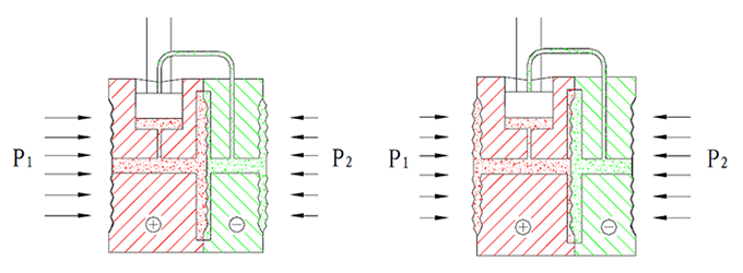
Fig. 4 Schematic diagram of positive cavity overload Fig. 5 Schematic diagram of negative cavity overload
This anti-overload design method effectively protects the long-term stability of the single crystal silicon chip, especially in the presence of water hammer phenomenon in the working conditions more prominent.
2.3 Superior range ratio adjustable performance
As the output signal of the single crystal silicon chip is large, in the 5V constant voltage source excitation of its typical range output reached 100mV, so that the back-end electronic circuit and software is easier to realize the signal compensation and amplification processing. Compared to metal capacitive pressure, differential pressure transmitter, single crystal silicon principle of pressure, differential pressure transmitter range ratio performance is very superior, its common pressure transmitter range adjustable ratio of 100:1, micro-differential pressure transmitter adjustable range ratio of 10:1. by the range compression can still maintain a higher basic accuracy, significantly broaden the single crystal silicon pressure transmitter can be adjusted range, the application of the more user-friendly and meaningful. Convenient and meaningful for user applications.
As shown in Table 1, three sampled differential pressure transmitter after 10:1 range reduction and 100:1 range reduction after the accuracy assessment results. The full range is 0-250kPa, the range after 10 times compression is changed to 0-25kPa, and the range after 100 times compression is changed to 0-2.5kPa. From the results of the experiment, it can be seen that when compressed by 10 times the range ratio, the basic error is 0.019%, 0.012%, 0.025%, and still able to keep the accuracy due to 0.05 level; when compressed by 100 times the range ratio, the basic error is 0.019%, 0.012%, 0.025%, and still able to keep the accuracy due to 0.05 level; when compressed by 100 When compressed 100 times the range ratio, the basic error is 0.147%, 0.219%, 0.197%, which can still be better than the accuracy of 0.25 level.
As shown in Table 2, three sampled pressure transmitters after 10:1 range reduction and 100:1 range reduction after the accuracy assessment results. The full range is 0-40MPa, the range after 10 times compression is changed to 0-4MPa, and the range after 100 times compression is changed to 0-400kPa. From the results of the experiment, it can be seen that when the compression of 10 times the range ratio, the basic error is 0.041%, 0.047%, 0.034%, respectively, which can still achieve the accuracy of 0.05; when the compression of 100 times the range ratio, the basic error is 0.041%, 0.047%, 0.034%, respectively, which can still achieve the accuracy of 0.05; when the compression of 100 times the range When compressed 100 times the range ratio, the basic error is 0.15%, 0.063%, 0.153%, which can still be better than 0.25 level accuracy.
2.4 Superior pressure hysteresis performance
Pressure hysteresis characteristics, also known as the return error characteristics, commonly known as the return difference, for pressure, differential pressure transmitter is a more important assessment indicators. The size of the return error directly affects the measurement accuracy and long-term drift performance of the transmitter. As shown in Figure 5, this is a typical monocrystalline silicon error curve and metal capacitance error curve comparison schematic. As can be seen from the figure, the monocrystalline silicon principle of the sensor's linear error curve of the return difference is very small, the upper stroke and the lower stroke almost overlap, and its return difference is basically negligible; while the metal capacitive principle of the linear error curve of the return difference is larger, the upper stroke and the lower stroke is open, which directly affects the output accuracy of the transmitter.
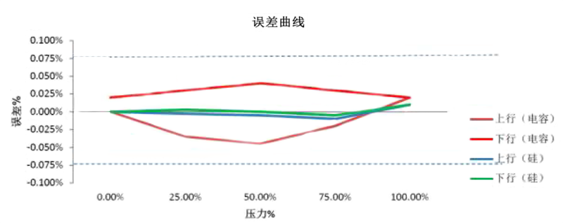
Fig. 5 Example of error curve
2.5 Special hydrostatic characteristics
Differential pressure transmitter in the measurement of tank level or pipeline flow, if the static pressure effect is not corrected or compensated, will bring large errors to the measurement, especially in the level range is small or relative flow rate is small, the impact is more huge. For example, a capacitive differential pressure transmitter with the throttle device together with the composition of differential pressure flowmeter, in the 32MPa working static pressure conditions of its full-scale static pressure error of ≤ ± 2% FS, although the zero error, can be eliminated by adjusting the zero, but the full output error can not be avoided. Therefore, this static pressure error directly affects the flow test, and the amount of influence is large. In this application condition, the static pressure performance of the differential pressure transmitter is especially important, if the static pressure error is compensated, or its own static pressure error is very small, then its measurement accuracy will be greatly improved.
Differential pressure transmitter using a unique monocrystalline silicon chip encapsulation process, after encapsulation of the inner and outer cavities to achieve pressure balance. As shown in Figure 6 for the monocrystalline silicon wafer packaging schematic, when there is a working static pressure loaded to the measurement of the wafer's positive and negative cavities, the working static pressure through the wafer outside the positive cavity silicone oil and the wafer inside the negative cavity silicone oil balanced loaded to the measurement of the wafer, and to achieve a mutual offset, thus making the measurement of the wafer on the working static pressure of the bending deformation of a very small. This treatment significantly improves the performance of the differential pressure transmitter in terms of static pressure influence.
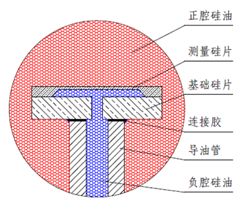
Fig. 6 Monocrystalline silicon wafer packaging diagram
In the application of micro differential pressure transmitter, due to the micro differential pressure signal is too small, for the impact of static pressure caused by the impact of very sensitive, as mentioned above, the unique package design and process can not be eliminated or weakened the amount of static pressure impact. Therefore, in order to address this issue, YR-ER101 differential pressure transmitter in its sensor internal integration of an adiabatic pressure sensor can measure the static pressure of the work, as shown in Figure 7 for the structure of the YR-ER101 differential pressure sensor schematic. This adiabatic pressure sensor can measure the working static pressure signal real-time feedback to the internal microprocessor, the microprocessor uses the working static pressure axis to automatically correct the microdifferential pressure output signal, so as to achieve the function of static pressure compensation. The unique packaging process and the addition of an adiabatic pressure sensor significantly improve the performance of the CY-ER101 differential pressure transmitter's operating static pressure, thus ensuring the accuracy and high stability of the measurement of the differential pressure transmitter.
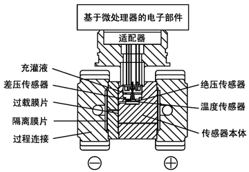
Fig. 7 Structure of monocrystalline silicon differential pressure sensor
2.6 Special diaphragm processing technology
Compared with the U.S. Rosemount's metal capacitive sensors, Yokogawa's monocrystalline silicon sensors, European ABB's silicon differential pressure sensors and other isolation ring diaphragm welding, differential pressure sensors use a more advanced non-isolated ring hygienic diaphragm welding method. This hygienic diaphragm welding method makes the weld seam smooth, no gap, no dead space, can meet the direct welding of a variety of materials diaphragm, such as 316L, Hastelloy C, Tantalum diaphragm, Monel diaphragm, due to the absence of a gap in the presence of the liquid can also be directly in the liquid side of the gold-plating and spraying of PTFE and other processing technology. This design and special treatment process makes the differential pressure transmitter liquid range greatly extended and expanded, and greatly enhance the corrosive occasions the service life of the differential pressure transmitter.
2.7 Special ultra-high-temperature remote transmission design and realization
As we all know, pressure, differential pressure transmitter in the application of high temperature telemetry box in the application process, when the medium temperature exceeds 350 ℃ application of the existence of a huge safety hazard, more likely to appear silicone oil vaporization, data distortion or life expectancy decline and so on, which requires the application of the site of the medium has a certain working static pressure and thus the formation of a backpressure to ensure that the normal operation of the diaphragm box. This causes the pressure, differential pressure transmitter telemetry level measurement application range is limited. From the use of ultra-high-temperature media measurement technology, the measurable temperature of the medium has reached 400 ℃.
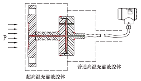
Figure 8 Ultra-high temperature remote transmission structure principle diagram
As shown in Fig. 8, the structure of this ultra-high-temperature teleportation is schematic. This ultra-high-temperature teleportation structure is divided into ultra-high-temperature filling liquid and ordinary high-temperature filling liquid two chambers, the two chambers welded between the isolation diaphragm, and in the ultra-high-temperature filling cavity is set up with a heat sink rod. The ultra-high-temperature filling fluid in direct contact with the medium can withstand a high temperature of 400℃, but the viscosity of the ultra-high-temperature filling fluid is high, which is not suitable for filling the capillary tube for pressure transfer. Therefore, further pressure transfer through the intermediate isolation diaphragm and ordinary high-temperature filling fluid cavity can ensure the limited pressure transfer and fast response. And the high temperature heat is transferred to the ordinary high temperature filling cavity after heat dissipation, the temperature has been greatly reduced, which can ensure the normal use of the ordinary high temperature filling liquid cavity. This approach broadens the application range of high-temperature telemetry transmitters and improves the reliability and life of ultra-high-temperature telemetry transmitters.
2.8 Realization of performance index and reliability
Through the above introduction and analysis of the series of products technology, the author briefly explains the monocrystalline silicon high stability pressure, differential pressure transmitter project to realize the process. Manufacturers from the monocrystalline silicon principle chip selection, monocrystalline silicon wafer stress-free packaging, the elimination of backhaul error, the static pressure effect of the attenuation of the range ratio of the amplification of the special treatment process to meet the liquid surface as well as the expansion of ultra-high-temperature measurements, and so on, in order to enhance the full performance of high-stability pressure, differential pressure transmitter, the accuracy level and reliability. Through the above multiple ways of technology introduction and digestion, and then join the new design, make the YR-ER100 series of high stability pressure, differential pressure transmitter has reached the advanced level, its main technical advantages are shown as follows:
(1) The accuracy level reaches 0.05 grade, and obtains the manufacturing license of measuring instruments, which reaches the advanced level;
(2) micro-differential pressure transmitter adopts the unique double overload protection diaphragm proprietary technology, up to ± 0.075% of the high accuracy of measurement, the maximum working static pressure up to 16MPa, the smallest measurement of the differential pressure of -50Pa ~ 50Pa, the first domestic and foreign technology level;
(3) The maximum working static pressure of the differential pressure transmitter can reach 40MPa, and the maximum one-way overload pressure can reach 40MPa;
(4) Differential pressure sensor internal optional package adiabatic pressure sensor, can be used for on-site work static pressure measurement and display, can also be applied to static pressure compensation, so that the monocrystalline silicon pressure transmitter static pressure performance is very good, so that the typical specifications of the static pressure error is excellent for ≤ ± 0.05%/10MPa. At the same time, due to the integration of the internal adiabatic pressure sensor to ensure that the success of the development of the YR-ER100 multi-parameter transmitter can be widely used in the field of gas flow measurement.
(5) The high sensitivity temperature sensor integrated inside the pressure and differential pressure sensor makes the transmitter's temperature performance excellent, especially for ≤±0.04%/10K;
(6) 6kPa and 40kPa micro-pressure range gauge pressure / adiabatic pressure transmitter can be selected from the unique no pressure loss overload protection diaphragm proprietary technology, unidirectional overpressure of up to 7MPa, significantly expanding the micro-pressure sensor special areas of application;
(7) Typical specifications of the long-term zero drift amount of ≤ ± 0.1% / 3 years, and through 120,000 times 90% of the range of the ultimate pressure fatigue test, to achieve the ability of 10 years maintenance-free;
(8) Realized an extremely wide measuring range of 0-100Pa ~ 60MPa, ZUI high 100:1 adjustable range ratio output;
(9) The remote transmitter adopts advanced ultra-high temperature proprietary technology, which can be applied to 400℃ ultra-high temperature measurement occasions, breaking through the bottleneck of the application and measurement of remote transmission products.