◆Features
2-wire output 4-20mA, strong anti-interference ability;.
Save the cost of compensation wire and installation of temperature transmitter.
Safe and reliable, long service life.
Cold end temperature automatic compensation, non-linear correction circuit ;◆ Features
Working Principle
Thermocouple (resistance) in the working state of the measured thermal potential (resistance) changes, through the temperature transmitter bridge generates an unbalanced signal, after amplification, converted into 4-20mA signal to the work of the instrument, the work of the instrument will display the corresponding temperature value.
Explosion-proof thermocouple (resistance) using the gap explosion-proof principle, when an explosion occurs in the cavity, can be quenched and cooled through the joint surface gap, so that the flame and temperature after the explosion can not be transmitted to the outside of the cavity, so as to carry out temperature measurement. The thermal potential (resistance value) generated by thermocouple (resistance) passes through the bridge of temperature transmitter to generate unbalanced signal, which is converted into 4-20mA DC signal after amplification and given to the worker's instrument, which displays the corresponding temperature value.
◆ Main Technical Parameters
Product implementation standard
IEC584
IEC751
IEC1515
JB/T5518-91
JB/T7391-94
Measuring range and tolerance
1)Measuring range and tolerance of RTDs
| Model No. | Graduations | Temperature range ℃ | Accuracy Class | tolerance (allowed error) |
| WZPB | Pt100 | -200-+500 |
Class A Class B
|
±(0.15+0.002ItI)
±(0.30+0.005 ItI)
|
| WZCB | Cu50 Cu100 | -50-+100 |
|
±(0.30+0.005 ItI) |
| Model No. | Graduations | Tolerance level | |||
| I | II | ||||
| Tolerance | Temperature range ℃ | Tolerance | Temperature range | ||
| WRNB | K | ±1.5℃ | -40-375 | ±2.5℃ | -40-333 |
| ±0.004 ItI | 375-1000 | 0.0075 ItI | 333-1200 | ||
| WRMB | N | ±1.5℃ | -40-375 | ±2.5℃ | -40-333 |
| ±0.004 ItI | 375-1000 | 0.0075 ItI | 333-1200 | ||
| WREB | E | ±1.5℃ | -40-375 | ±1.5℃ | -40-333 |
| ±0.004 ItI | 375-800 | 0.004 ItI | 333-900 | ||
| WRFB | J | ±1.5℃ | -40-375 | ±1.5℃ | -40-333 |
| ±0.004 ItI | 375-750 | 0.004 ItI | 333-750 | ||
| WRCB | T | ±1.5℃ | -40-125 | ±1℃ | -40-133 |
| ±0.004 ItI | 125-350 | 0.0075 ItI | 133-1000 | ||
Output signal: 4-20 mA, load resistance 250, transmission line resistance 100
Output method: 2-wire
Accuracy level:
Temperature transmitter accuracy level: 0.1 0.2 0.5
Display accuracy level: analog indication type 2.5 level; digital display type 0.5 level.
Power supply: 24V.DC±10℅.
Protection grade: IP65
Explosion-proof grade:
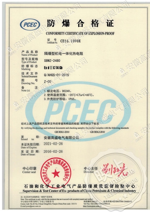
Explosion-proof: dⅡBT4 dⅡCT5 dⅡCT6
Intrinsically safe: iaⅡCT6
Insulation resistance: the insulation resistance between the output terminals of the instrument and the shell should be not less than 50.
Thermal response time:
When there is a step change in temperature, the current output signal of the instrument changes to the equivalent of the step change of 50% of the time required, usually expressed in t0.5 when the temperature transmitter step response stabilization time does not exceed one-fifth of the thermocouple (resistance) thermal response stabilization time of t0.5, the thermocouple (resistance) thermal response time as the instrument's thermal response time; when the temperature transmitter step thermal response stabilization time does not exceed the thermocouple (resistance) thermal response time as the instrument's thermal response time; when the temperature transmitter step thermal response stabilization time does not exceed the thermocouple (resistance) thermal response stabilization time of t0.5, the thermocouple (resistance) thermal response time as the instrument's thermal response time. When the step thermal response stabilization time of the temperature transmitter does not exceed one-half of the thermocouple (resistance) thermal response stabilization time t0.5, the thermal response time of the temperature transmitter is used as the thermal response time of the instrument.
Basic error:
The basic error of the instrument shall not exceed the synthesized error of the basic error of the thermocouple (resistance) and temperature transmitter.