
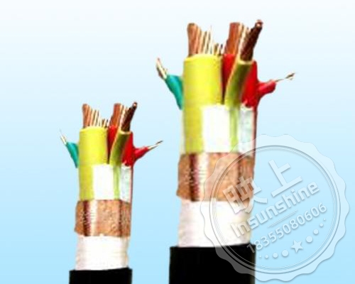

Copper wire shielded power cable for inverter

Copper Tape Shielded Power Cable for Inverter

structure plan

High-temperature cables for inverters
Note: Our company can according to customer site requirements: research and development of customized production of various types and specifications of cables (including high-temperature frequency conversion cable).
Tel: Mr. Chen 18355080606 (micro letter with number)
Inverter power cable standard and technical parameters
Rated voltage 1KV to 3KV inverter power cable
1 Scope
This standard specifies the product name, technical requirements, test methods, inspection rules and packaging and transportation of power cables for inverters.
This standard applies to the rated voltage 0.6/1kV and 1.8/3kV inverter power cables (hereinafter referred to as inverter cable).
2 Normative references
The provisions in the following documents become the provisions of this standard through the citation of this standard. Where the cited documents are dated, all subsequent revision sheets (excluding the contents of the errata) or revised versions are not applicable to this standard, however, the parties who have reached an agreement under this standard are encouraged to study whether the latest versions of these documents can be used. Where the cited documents are not dated, the latest version is applicable to this standard.
GB/T 2900.10-2001 Electrotechnical terminology Cables (IEC 60050-461:2008, IDT)
GB/T 2951.11-2008 General test methods for insulating and sheathing materials for cables and optical fiber cables Part 11: General test methods - Measurement of thickness and external dimensions - Mechanical property test (IEC 60811-1-1:2001, IDT)
GB/T 2951.12-2008 General test method for insulating and sheathing materials for cables and optical fibers Part 12: General test method - Thermal aging test method (IEC 60811-1-2:1985, IDT)
GB/T 2951.13-2008 General test method for insulating and sheathing materials for cables and optical fibers Part 13: General test methods - Density determination - Water absorption test - Shrinkage test (IEC 60811-1-3:2001, IDT) IDT)
GB/T 2951.21-2008 General test method for insulating and sheathing materials for cables and optical fiber cables Part 21: Special test method for elastomer compounds - Ozone resistance test - Thermal extension test - Mineral oil immersion test (IEC 60811-2-1:2001, IDT) -1:2001, IDT)
GB/T 2952.3-2008 Cable sheathing Part 3: General sheathing for non-metallic sheathed cables
GB/T 3048.4-2007 Test methods for electrical properties of electrical wires and cables Part 4: DC resistance test for conductors
GB/T 3048.5-2007 Test methods for electrical properties of electrical wires and cables Part 5: Insulation resistance test
GB/T 3048.8-2007 Test method for electrical properties of wire and cable, Part 8: AC voltage test
(IEC 60060-1:1989, NEQ)
GB/T 3048.9-2007 Test Methods for Electrical Performance of Wire and Cable Part 9: Spark test of insulated core
GB/T 3956-2008 Conductors of cables (IEC 60228:2004, IDT)
GB/T 6995.3-2008 Wire and cable identification marking methods Part 3: Wire and cable identification marking
GB/T 6995.5-2008 Methods of identification marking for wires and cables Part 5: Identification marking for insulated cores of power cables
GB/T 12706.1-2008 Extruded insulated power cables and accessories for rated voltages from 1kV (Um=1.2kV) to 35kV (Um=40.5kV) Part 1: Cables with rated voltages of 1kV (Um=1.2kV) and 3kV (Um=3.6kV)
GB/T 17737.1-2000 Radio-frequency cables Part 1: General specifications - General provisions, definitions, requirements and test methods (IEC 61196-1:2005, IDT)
GB/T 19666-2005 Flame-retardant and fire-resistant wires and cables
JB/T 8137-1999 Wire and cable delivery tray
JB/T 10696.7-2007 Test Methods for Mechanical and Physical-Chemical Properties of Wire and Cable Part 7: Tear Resistance Test
3 Definitions
This standard adopts GB/T 2900.10 and the following definitions.
3.1 Rated voltage rated voltage
The rated voltage of the cable is the cable design, use and electrical performance test with the reference voltage.
Rated voltage is expressed in U0/U, the unit is kV.
U0 that any of the main insulated conductors and “ground” (metal shielding, metal jacket or surrounding medium) between the voltage effective value; U for multi-core cable or single-core cable system any two-phase conductor voltage between the effective value.
In the AC system, the rated voltage of the cable shall be at least equal to the nominal voltage of the system using the cable, and this condition applies to both U0 and U value; in the DC system, the nominal voltage of the system shall be not more than 1.5 times the rated voltage of the cable.
The operating voltage of the system shall be not greater than 1.1 times the nominal voltage of the system.
3.2 Batch
Batch refers to the number of products of the same type and specification in one order. If there are products of different models and specifications in one order, the different models and specifications shall be regarded as different batches.
3.3 Definition of tests
3.3.1 Routine tests routine tests (symbol R)
Tests carried out by the manufacturer on all manufactured lengths of finished cables to check that all cables comply with the specified requirements.
3.3.2 sample tests sample tests (symbol S)
Tests carried out by the manufacturer, at a specified frequency, on specimens of finished cables, or on certain components taken from finished cables, to check that the cables comply with the specified requirements.
3.3.3 Type tests (symbol T)
Tests carried out in accordance with general commercial principles on a type of cable covered by this specification prior to supply to demonstrate that the cable has good performance for the intended conditions of use. The test is characterized by: unless the cable material, design or manufacturing process changes may change the characteristics of the cable, the test has been done after the need to redo.
4 Cable type and product indication
4.1 Designation
4.1.1 Product series code
Inverter cable BP
4.1.2 Conductor designation
Type 1 single conductor (may be omitted)
Category 2 7 conductors soft construction (B)
Category 5 conductor (soft structure) R
4.1.3 Insulation designation
Cross-linked polyethylene/polyolefin YJ
Silicone rubber G
Ethylene Propylene Rubber Insulation E
Polyvinyl chloride V
4.1.4 Sheath designation (including extruded liner, barrier sleeve, etc.)
Polyethylene/polyolefin Y
Cross-linked polyolefin YJ
Silicone rubber G
Low smoke halogen free polyolefin sheath E
Polyvinyl chloride V
ZA (Class A Flame Retardant), ZB (Class B Flame Retardant), ZC (Class C Flame Retardant), ZR (Flame Retardant)
Low smoke halogen free flame retardant WDZ
4.1.5 Metal shielding code
Copper wire sparse winding SP
Copper wire braid P
Tinned copper wire braid P1
Copper tape P2
Aluminum-plastic composite tape wrapped P3
Copper wire braided copper tape wrapped shield PP2
4.1.6 Metal Armor Designation
Double steel belt armor 22
Fine round steel wire sparsely wound armor 32
Coarse round steel wire sparse winding armor 42
Galvanized steel wire braid armor 92
Polyvinyl chloride sheath V
Polyethylene sheath 3
4.2 Representation
The product is indicated by model number, specification and number of this standard.
The composition and arrangement order of the product model number is shown in Fig. 1.
A
a) Copper core cross-linked polyethylene insulated copper wire braided shielded PVC sheathed cable for inverter, rated voltage 0.6/1kV, 3+3 cores, nominal cross section 16mm2, neutral cross section 4mm2 is indicated as:
BPYJVP-0.6/1kV 3×16+3×4 mm2
b) Copper core cross-polyethylene insulated copper tape wound shielded polyolefin sheathed low smoke halogen free flame retardant cable for inverter, rated voltage 0.6/1kV, 3+3 cores, nominal cross section 95mm2, neutral cross section 16mm2 is indicated as:
WDZ-BPYJYP2 - 0.6/1kV 3×95+3×16 mm2
Table 1
c) Copper core ethylene propylene rubber insulated copper wire braid shielded silicone rubber sheathed cable for inverter, rated voltage 0.6/1kV, 3+3 cores, nominal cross section 150mm2, neutral cross section 25mm2 is expressed as:
BPEGP-0.6/1kV 3×150+3×25 mm2
d) Copper core silicone rubber insulated copper tape wound shielded silicone rubber sheathed inverter cable, rated voltage 1.8/3kV, 3 equal cores, nominal cross-section 240mm2, neutral cross-section 50mm2 denoted as:
BPGGP2-1.8/3kV 3×240 mm2
4.3 Common model names of cables
Common model names of cables are shown in Table 1
|
model number |
name (of a thing) |
|
BPGG |
Silicone rubber insulated and sheathed copper wire braid shielded high temperature resistant inverter power cable. |
|
BPGGP2 |
Silicone rubber insulated and sheathed copper tape wound shielded high temperature resistant inverter power cable. |
|
BPGGPP2 |
Silicone rubber insulated and sheathed copper wire braided copper tape wound shielded high temperature resistant inverter power cable. |
|
BPGGP3 |
Silicone rubber insulated and sheathed aluminum polyester composite film wound and shielded high temperature resistant inverter power cable. |
|
BPGVFP |
Silicone rubber insulated nitrile sheathed copper wire braid shielded high temperature resistant inverter power cable. |
|
BPGVFP2 |
Silicone rubber insulated nitrile sheathed copper tape wound shielded high temperature resistant inverter power cable. |
|
BPGVFPP2 |
Silicone rubber insulated nitrile sheathed copper wire braided copper tape wound shielded high temperature resistant inverter power cable. |
|
BPGVFP3 |
Silicone rubber insulated nitrile sheathed aluminum polyester composite film wound and shielded high temperature resistant inverter power cable. |
|
BPFFP |
Fluorine 46 insulated and sheathed copper wire braid shielded high temperature resistant inverter power cable. |
|
BPFFP2 |
Fluorine 46 insulated and sheathed copper tape wound shielded high temperature resistant inverter power cable. |
|
BPFFPP2 |
Fluorine 46 insulated and sheathed copper wire braided copper tape wound shielded high temperature resistant inverter power cable |
|
BPFFP3 |
Fluorine 46 insulated and sheathed aluminum polyester composite film wound and shielded high temperature resistant inverter power cable. |
|
BPVVP |
PVC insulated and sheathed copper wire braid shielded inverter power cables. |
|
BPVVP2 |
PVC insulated and sheathed copper tape wound shielded inverter power cables. |
|
BPVVPP2 |
PVC insulated and sheathed copper wire braided copper tape wound shielded inverter power cable. |
|
BPVVP3 |
PVC insulated and sheathed aluminum polyester composite film wound and shielded inverter power cables. |
|
BPYJVP |
Cross-linked polyethylene insulated PVC sheathed copper wire braided shielded inverter power cable. |
|
BPYJVP2 |
Cross-linked polyethylene insulated PVC sheathed copper tape wound shielded inverter power cable. |
|
BPYJVPP2 |
Cross-linked polyethylene insulated PVC sheathed copper wire braided copper tape wound shielded inverter power cable. |
|
BPYJVP3 |
Cross-linked polyethylene insulated PVC sheathed aluminum polyester composite film wound shielded inverter power cable. |
Remarks: The copper wire in the conductor core can be tinned P1, add ZR before the model number of flame-retardant cables, and add R for soft-structured cables.
4.4 Cable specifications
Cable specifications are given in Table 2. main core cross section
|
model number |
core number (of a fiber) |
Nominal cross section mm2 |
|
All Models |
3+3 3+1 1 |
4,6,10,16,25,35,50,70,95, 120,150,185,240 |
Grounding core cross section
|
Nominal cross section of main core mm2 |
Grounding core section mm2 |
|
4 |
1(0.75) |
|
6 |
1.5(1) |
|
10 |
2.5(1.5) |
|
16, 25 |
4(2.5) |
|
35 |
6 |
|
50, 70 |
10 |
|
95 |
16 |
|
120, 150 |
25 |
|
185 |
35 |
|
240 |
50(35) |
Technical Requirements
4.5 Materials
4.5.1 Insulation mixes
Insulation mixes covered by this standard, their designations and maximum conductor temperatures are listed in Table 3.
1) Insulation mixes
|
Insulation mixes |
nicknames |
Maximum conductor temperature/°C |
|
|
normal operation |
When short-circuited (max. 5s duration) |
||
|
polyvinyl chloride (PVC) |
PVC/A |
70 |
160 |
|
crosslinked polyethylene |
XLPE |
90 |
250 |
|
ethylene propylene rubber |
EPR |
90 |
250 |
|
Silicone Rubber Insulation |
G |
180 |
350 |
|
fluoroplastic |
F |
200 |
360 |
|
Partial Difluorinated Plastics |
F4 |
125 |
250 |
4.5.2 Sheath mixtures
The maximum conductor temperatures of different types of sheath mixtures of this standard are listed in Table 4.
2) Maximum conductor temperatures for cables with different types of sheath mixtures
|
Jacket Mix |
nicknames |
Maximum conductor temperature during normal operation/°C |
|
polyvinyl chloride (PVC) |
ST1 |
80 |
|
ST2 |
90 |
|
|
polyethylene |
ST3 |
80 |
|
ST7 |
90 |
|
|
Halogen-free flame retardant materials |
ST8 |
90 |
|
Elastomers (TPE, TPU, chlorinated polyethylene, etc.) |
SE1 |
85 |
|
silicone rubber |
G |
180 |
4.6 Conductor
4.6.1 Conductor should be in line with GB/T 3956 in the first or second type of bare annealed copper conductor or annealed copper conductor plated with a metal layer, or the fifth type of bare copper conductor or annealed copper conductor plated with a metal layer.
4.6.2 The surface of the conductor shall be smooth and free from burrs, sharp edges, and raised or broken monofilaments that impair the shielding and insulation. Conductor 20 ℃ DC resistance should be consistent with the provisions of GB / T 3956.
4.6.3 The conductor surface is allowed to use non-hygroscopic tape material for overlapping winding or longitudinal package, the performance of the tape is not assessed.
4.7 Insulation
4.7.1 Insulation shall be one of the extruded solid dielectrics listed in Table 3. Polyvinyl chloride insulation, cross-linked polyethylene insulation and ethylene-propylene rubber insulation mechanical and physical properties should be consistent with the provisions of GB/T 12706.1; silicone rubber insulation and cross-linked polyolefin insulation mechanical and physical properties in line with the provisions of Appendix A, Table A.1 and Table A.4.
4.7.2 Insulation thickness of the nominal value should be consistent with the provisions of Table 5 to Table 6. Insulation thickness of the average value is not less than the nominal value, insulation at the thinnest point of the thickness should not be less than 90% of the nominal value -0.1mm.
4.7.3 Insulation should be tightly extruded on the conductor, the section without visually visible bubbles and impurities, the appearance of round and easy to peel off with the conductor.
4.7.4 Insulated wire core should be in accordance with the provisions of GB / T 3048 subjected to the provisions of Table 7 of the frequency spark test as an intermediate check.
4.7.5 The main core and neutral core identification mark the same, can use digital, ribbon or color identification, are in line with the provisions of GB / T 6995, but can also be determined in consultation with the user or according to user requirements.
3) Nominal thickness of insulation
|
Nominal cross-section mm2 |
Nominal thickness of insulation at rated voltage U0/U(Um)/mm |
|||
|
Nominal thickness of ethylene propylene rubber, silicone rubber insulation |
Thickness of cross-linked polyethylene insulation |
|||
|
0.6/1(1.2)kV |
1.8/3(3.6)kV |
0.6/1(1.2)kV |
1.8/3(3.6)kV |
|
|
0.75,1.0,1.5,2.5 |
1.0 |
— |
0.7 |
— |
|
4,6 |
1.0 |
— |
0.7 |
— |
|
10,16 |
1.0 |
2.2 |
0.7 |
2.0 |
|
25,35 |
1.2 |
2.2 |
0.9 |
2.0 |
|
50 |
1.4 |
2.2 |
1.0 |
2.0 |
|
70,95 |
1.6 |
2.4 |
1.1 |
2.0 |
|
120 |
1.6 |
2.4 |
1.2 |
2.0 |
|
150 |
1.8 |
2.4 |
1.4 |
2.0 |
|
185 |
2.0 |
2.4 |
1.6 |
2.0 |
|
240 |
2.2 |
2.4 |
1.7 |
2.0 |
|
300 |
2.4 |
2.4 |
1.8 |
2.0 |
4) Nominal thickness of insulation
|
Nominal cross-section mm2 |
Nominal thickness of insulation at rated voltage U0/U(Um)/m |
|
|
Nominal thickness of PVC/A insulation |
||
|
0.6/1(1.2)kV |
1.8/3(3.6)kV |
|
|
0.75,1.0 |
0.8 |
— |
|
1.5,2.5 |
0.8 |
— |
|
4,6 |
1.0 |
— |
|
10,16 |
1.0 |
2.2 |
|
25,35 |
1.2 |
2.2 |
|
50 |
1.4 |
2.2 |
|
70 |
1.4 |
2.2 |
|
95 |
1.6 |
2.4 |
|
120 |
1.6 |
2.4 |
|
150 |
1.8 |
2.4 |
|
185 |
2.0 |
2.4 |
|
240 |
2.2 |
2.4 |
|
300 |
2.4 |
2.4 |
5) Spark test voltage
|
Insulation nominal thickness/mm |
Test voltage/kV |
|
0.5<δ≤1.0 |
6 |
|
1.0<δ≤1.5 |
10 |
|
1.5<δ≤2.0 |
15 |
|
2.0<δ≤2.5 |
20 |
|
2.5<δ |
25 |
4.8 Cores and fillers of cables
4.8.1 Cable cores
4.8.1.1 The cable core is divided into 3 equal core structure and 3 + 3 (3 equal cross-section of the main core and 3 equal cross-section of the sub-core) structure, the insulated wire core should be stranded into the cable, stranded in the right direction, hard structure cable stranded pitch should be not more than 40 times the stranded outside diameter, soft structure cable stranded pitch should be not more than 20 times the stranded outside diameter.
4.8.1.2 The 3+3 structure wire core shall be arranged according to the color sequence of the main insulation core to ensure that the grounding core is in the gap between the two adjacent main cores.
4.8.1.3 The gaps between the cable insulation cores are allowed to be filled tightly with a suitable material suitable for the operating temperature of the cable and compatible with the cable insulation.
4.8.2 Cable cores are permitted to be tightened with suitable tape after forming the cable.
4.8.3 Cables without extruded liner are permitted to be wrapped around two layers of polyester wrapping tape with an overlap of not less than 50% after cable formation, but the performance of the polyester tape may not be assessed.
4.8.4 Metal armored, concentric conductor, metal shielded multi-core cables shall be extruded with one layer of inner liner on the core.
4.9 Inner liner layer
4.9.1 The liner layer is extruded or wrapped.
4.9.2 The material used for the inner liner shall be suitable for the operating temperature of the cable and compatible with the cable insulation.
4.9.3 Extruded liner layer approximate thickness should be selected from Table 8 (the assumed diameter required for the calculation according to GB/T 12706.1 Appendix A (Appendix to the standard), according to the three-core calculation, the same below).
4.9.4 Cable core assumed diameter of 40mm and below, the approximate thickness of the lining layer around the package to take 0.4mm; if greater than 40mm, then take 0.6mm.
6) Extruded liner thickness
|
Assumed diameter of cable core/mm |
Approximate thickness of extruded liner/mm |
|
|
— |
≤25 |
1.0 |
|
>25 |
≤35 |
1.2 |
|
>35 |
≤45 |
1.4 |
|
>45 |
≤60 |
1.6 |
|
>60 |
≤80 |
1.8 |
|
>80 |
— |
2.0 |
4.10 Metal general shielding layer
4.10.1 The cable must have a metal shielding layer, metal shielding has a copper wire braid shielding, copper tape wrapped shielding, tinned copper wire braid shielding, copper wire braid and copper tape wrapped composite shielding and other structural types. Inverter cable core structure for the 3 core, total shielding should be not less than the total cross-section of the neutral core cross-section.
4.10.2 Braided shielding
4.10.2.1 Braid diameter
Regardless of the type of metal, the nominal diameter of braided wire in accordance with the provisions of Table 9:
7) Nominal diameter of round braided wire
|
Assumed diameter before armoring d/mm |
Armored round metal wire nominal diameter/mm |
|
d≤10 10<d≤30 d>30 |
0.15 0.20 0.30 |
4.10.2.2 Braiding density
Copper wire braided shielding shall have a braiding density of not less than 80%.
Braiding density of the braided layer is calculated according to formula 1
P = (2p-p2) × 100 ........................( 1)
Formula (1) in: P - woven layer braided density, percent
p - unidirectional coverage factor
Type (2) in: D - knitting layer of the pitch circle diameter, mm;
d - diameter of the braid, mm;
m - the number of spindles in the same direction of the braiding machine;
n - the number of braided threads per spindle (the average number of braided threads in the upper and lower spindles when the upper and lower spindles are not the same);
L--weaving pitch, mm;
4.10.3 Copper tape winding using a single layer of overlap winding, overlap rate of not less than 15%, copper tape thickness of not less than 0.1mm.
4.10.4 Copper wire winding total shielding, the interval between the copper wire should not be less than 4mm, the shielding can be used outside the thin copper tape or wrapping tape gap winding and tying. Shielded copper wire DC resistance should be consistent with the provisions of GB/T 3956.
4.10.5 Shield and cable core allows a layer of internal padding.
4.11 Metal armor
4.11.1 Types of metal armor include flat wire armor, round wire armor, bimetallic tape armor. It is allowed to use galvanized steel wire and copper wire braid armoring for cables with conductor cross-section not exceeding 6mm2 by consensus between the manufacturer and the purchaser.
4.11.2 Material
Flat metal wire or round metal wire shall be galvanized steel wire, copper wire or tinned copper wire, aluminum or aluminum alloy wire.
Metal strip shall be steel strip, galvanized steel strip, aluminum or aluminum alloy strip, and the steel strip shall be hot-rolled or cold-rolled steel strip with commodity quality approval.
4.11.3 Isolation sleeve
When the metal layer under the armor is different from the armoring material, a material specified in Table 4 shall be used to extrude a layer of sheath to separate them. The nominal thickness Ts (in mm) of the extruded isolation sleeve shall be calculated according to the following formula:
Ts = 0.02 Du + 0.6
Where Du - the assumed diameter before extruding the isolation sleeve, mm.
4.11.4 Relationship between cable diameter and armor layer size
Round armored metal wire nominal diameter and armored metal tape nominal thickness should be not less than the values specified in Table 10 and Table 11, respectively.
8) Nominal diameter of round armored wire
|
Assumed diameter before armoring mm |
Armored wire nominal diameter mm |
|
d≤10 10<d≤15 15<d≤25 25<d≤35 35<d≤60 60<d |
0.8 1.25 1.6 2.0 2.5 3.15 |
9) Nominal thickness of armored metal tape
|
Assumed diameter before armoring/mm |
Nominal thickness of metal strip/mm |
|
|
Steel or galvanized steel strip |
Aluminum or Aluminum Alloy Strips |
|
|
d≤30 30<d≤70 70<d |
0.2 0.5 0.8 |
0.5 0.5 0.8 |
For cables with an assumed diameter greater than 15 mm before armoring, the nominal thickness of the flat metal wire shall be taken as 0.8 mm. Flat metal wire armoring shall not be used when the assumed diameter of the cable is 15 mm or less.
4.11.5 Round or flat wire armor
Metal wire armoring should be tight, even if the gap between adjacent wires is minimum. If necessary, a galvanized steel wire with a minimum nominal thickness of 0.3 mm may be sparsely wound around the flat and round wire armour.
4.11.6 Bimetallic belt armor
Metal belt armor should be spiral wrapped two layers, the middle of the outer layer of metal tape roughly in the inner layer of metal tape gap above the gap should not be greater than 50% of the width of the tape.
4.11.7 The armored metal wires and tapes shall not exceed the amount by which the dimensions of the armored metal wires and tapes are less than the nominal dimensions specified in 5.6.4:
--Round metal wire: 5%;
--Flat metal wire: 8%;
--Metal tape: 10%.
4.12 Outer sheath
4.12.1 All cables shall have an outer jacket. The outer sheath shall normally be black in color and, by agreement between the manufacturer and the purchaser, shall be permitted to be non-black in color to suit the particular conditions under which the cable is to be used.
4.12.2 The outer sheath material shall be compatible with the cable operating temperatures specified in Table 4. The performance of PVC sheathing material complies with the provisions in GB/T 12706.1, and other sheathing performance complies with the provisions in Appendix A. In special conditions (for example, in order to prevent rodents, ants and other animals) to use the outer sheath, can be added to the formula of chemical additives. However, these additives should be harmless to humans and the environment.
4.12.3 Thickness
The nominal thickness value of the extruded sheath Ts (in mm) shall be calculated according to the following formula:
PVC sheath TS = 0.035D + 1.0
Silicone rubber sheath TS = 0.040D + 1.2
Where: D - the assumed diameter before extruding the isolation sleeve, mm.
The value calculated in the above formula should be rounded off to trim to 0.1mm.
No armored cable and sheath is not directly wrapped in armor on the cable, its single-core cable sheath thickness should not be less than the nominal thickness of 1.4mm, multi-core cable sheath thickness is not less than the nominal thickness of 1.8mm.
Sheath directly wrapped in the armor on the cable, the nominal thickness of the sheath should not be less than 1.8mm.
Covered in the smooth cylindrical surface of the outer sheath (such as extruded lining layer, metal sheath or insulation), the average value of its thickness measurement, should not be less than the nominal thickness of the provisions of the minimum measurement should not be less than 85% of the nominal value of the provisions of the nominal value of the - 0.1mm. Covered in the irregular cylindrical surface of the sheath (for example, no lining layer without the armored multicore cable sheath: extruded into the core void, or directly into the core void, or directly into the armored cable sheath, the thickness should be not less than 1.8mm nominal thickness. core voids, or directly over the armor, metal shield or concentric conductors) and the thickness of the isolation jacket shall be measured at a minimum of not less than 80% of the specified nominal value - 0.2 mm.
4.12.4 Sheath should be smooth surface, rounded, color and lustre is basically the same, the section should be free of visually visible bubbles and impurities, and other should be in line with the provisions of GB/T 2952.
5 finished cable
5.1 Structure size
5.1.1 The conductor structure of finished cables shall comply with the provisions of Article 5.2.1 of this standard.
5.1.2 Finished cable insulation thickness shall comply with the provisions of Article 5.3.2 of this standard.
5.1.3 Finished cable shall comply with the provisions of Article 5.4.1 of this standard.
5.1.4 Finished cable lining thickness shall comply with the provisions of Article 5.5.3 of this standard.
5.1.5 The total shielding layer of finished cables shall comply with the provisions of Article 5.6 of this standard.
5.1.6 Finished cable metal armor shall comply with the provisions of Article 5.7 of this standard.
5.1.7 Sheath thickness of finished cable shall comply with the provisions of Article 5.8 of this standard.
5.2 Electrical performance
5.2.1 The DC resistance of the conductor of finished cables shall comply with the provisions of Article 5.2.2 of this standard.
5.2.2 The insulation resistance of finished cables shall comply with the provisions of Table 12.
10) Insulation resistance
|
rated voltage |
Cable Specifications |
Insulation resistance at 20℃/MΩ-km |
Insulation resistance at operating temperature/MΩ-km |
|
0.6/1kV |
35mm2及以下 |
150 |
0.15 |
|
50~150mm2 |
100 |
0.10 |
|
|
185~400mm2 |
80 |
0.08 |
|
|
1.8/3kV |
35mm2及以下 |
250 |
0.25 |
|
50~150mm2 |
200 |
0.20 |
|
|
185~400mm2 |
150 |
0.15 |
|
|
|
|
|
|
Basic cable specifications and structural parameters
|
Core*Nominal cross section(mm2) |
Conductor structure (Roots*Diameter) mm
|
Maximum outer diameter of cable(mm) |
|
|
BPVVPP2 BPYJVPP2 |
BPGGPP2 |
||
|
3*4 |
1/2.26 |
13.5 |
15.5 |
|
3*6 |
1/2.78 |
14..0 |
16.0 |
|
3*10 |
7/1.35 |
19.0 |
21.0 |
|
3*16 |
7/1.70 |
22.0 |
24.0 |
|
3*25 |
7/2.15 |
25.0 |
26.5 |
|
3*35 |
7/2.52 |
26.0 |
35.5 |
|
3*50 |
10/2.52 |
28.5 |
40.0 |
|
3*70 |
14/2.52 |
31.5 |
43.5 |
|
3*95 |
19/2.52 |
36.5 |
50.0 |
|
3*120 |
24/2.52 |
40.0 |
56.0 |
|
3*150 |
30/2.52 |
45.0 |
60.0 |
|
3*185 |
37/2.52 |
47.0 |
67.0 |
|
3*4+3*0.75 |
1/2.26 |
14.5 |
16.5 |
|
3*6+3*1 |
1/2.78 |
15.0 |
17.0 |
|
3*10+3*2.5 |
7/1.35 |
20.8 |
22.0 |
|
3*16+3*2.5 |
7/1.70 |
23.0 |
25.0 |
|
3*25+3*4 |
7/2.15 |
28.0 |
27.5 |
|
3*35+3*6 |
7/2.52 |
32.0 |
36.5 |
|
3*50+3*10 |
10/2.52 |
37.0 |
41.0 |
|
3*70+3*10 |
14/2.52 |
41.6 |
44.5 |
|
3*95+3*16 |
19/2.52 |
47.0 |
51.0 |
|
3*120+3*25 |
24/2.52 |
50.1 |
57.0 |
|
3*150+3*25 |
30/2.52 |
52.0 |
61.0 |
|
3*185+3*35 |
37/2.52 |
58.5 |
68.0 |
Product Structure Schematic Diagram
5.2.3
5.2.4 Finished cable voltage resistance test
The finished cable shall be able to withstand the industrial frequency withstand voltage test specified in Table 13 for 5min without breakdown.
11) Finished product withstand voltage test voltage
|
Rated voltage/kV |
Test voltage/kV |
|
0.6/1 |
3.5 |
|
1.8/3 |
6.5 |
5.2.5 4U0 voltage test: rated voltage 0.6/1kV and 1.8/3kV cable insulation core should be subjected to ambient temperature, immersion in water for at least 1h, the test voltage of 4U0 frequency voltage test, the voltage should be gradually increased and lasted for 4h, the test process should not occur during the breakdown phenomenon. Specimen length (10-15)m.
5.2.6 Impulse voltage test: the cable should be impact voltage test, the test should be carried out in addition (10 ~ 15) m long finished cable, the test temperature is higher than the maximum operating temperature of the conductor 5 ℃ ~ 10 ℃. The test shall be conducted in accordance with GB/T 3048.13 steps to apply the impact voltage, rated voltage 0.6/1kV inverter cable with a peak impact voltage of 40kV; rated voltage 1.8/3kV inverter cable with a peak impact voltage of 50kV. for the absence of phase shielding of multi-core cables, the impact voltage shall be applied sequentially to each phase of the conductor between the conductor and the ground, and the other conductors are connected together and grounded. The other conductors are connected together and grounded. Each cable insulation core should be subjected to positive and negative polarity of each of the ten impact voltage without breakdown.
5.2.7 Shielding transfer impedance
Cable transfer impedance at 100MHz must be equal to or less than 1Ω/m;
Cable longitudinal interference voltage of 50mV when the ideal shielding coefficient is equal to or less than 0.66.
Shield layer transmission impedance according to GB/T 17737.1 were measured at 30MHz, 60MHz, 100 MHz three points of value.
5.3 Non-electrical performance
5.3.1 Mechanical and physical properties of the insulation of finished cables should be consistent with the requirements of Appendix A, Tables A.1 and A.4.
5.3.2 The mechanical and physical properties of the sheath of the finished cable shall meet the requirements of Appendix A, Tables A.2 and A.3.
5.3.3 If required by the user, the combustion performance of the finished cable meets the requirements of GB/T 19666 standard.
5.3.4 Finished cables should have continuous identification markings such as the name of the manufacturing plant, voltage, model and specifications. Signs should be consistent with the provisions of GB/T 6995.
6 test methods and inspection rules
6.1.1 The product should be qualified by the manufacturer's inspection before leaving the factory, each factory package should be accompanied by product quality inspection certificate.
6.1.2 The number of samples per batch according to the delivery batch of at least 1 sample, can also be specified by agreement between the supply and demand sides. Sampling test project results failed, should be doubled to take samples of unqualified items for the second test, still failed, the entire batch of products should be tested one by one.
6.1.3 Product appearance should be checked under normal vision batch by batch.
6.1.4 Product test items, test types, test methods according to Table 14.
7 Delivery length
7.1 Delivery length of cables with fixed length requirement of customers shall be delivered according to the agreed length.
7.2 Delivery length of other cables: 100m for circle, greater than 100m for disk.
7.3 Delivery of cables in integral multiples of the customer's shortest use length is permitted.
7.4 Delivery of finished cables of any length is permitted by mutual agreement.
7.5 The error in measuring the length of finished cables shall not exceed ±0.5%.
8 Packaging, transportation and storage
8.1 Packaging
The cables shall be properly packaged in accordance with the requirements of JB/T 8137 provisions of the cable tray for delivery. Cable ends should be reliably sealed, out of the cable ends should be extended outside the disk with a protective cover, out of the length should not be less than 300mm. weight does not exceed 80kg of short sections of cable, can be packaged in a circle. In order to prevent damage in storage and transportation, disk products should also be attached to the appropriate protection. Packing into a circle should be a certain strength of the band material multi-layer wrapping, and bundling firmly. Each cable end is well sealed with heat-shrink caps.
8.2 Transportation
Cable transportation shall not allow the cable tray to be in a flat position; shall not be rolled over long distances; shall not be subjected to impact, extrusion and any mechanical damage; long-distance transportation shall be prevented from prolonged exposure to the sun.
8.3 Each cable tray will be marked with the following:
a) Manufacturer;
b) Cable type, specification, voltage class;
c) Cable length, net weight, total weight;
d) Year and month of manufacture.
e) An arrow indicating the direction in which the cable tray rolls.
8.4 Quality inspection certificate
Table A. Sheath Material Non-Electrical Test Requirements
|
serial number |
Pilot project |
work unit (one's workplace) |
Mix code |
Test Methods |
|||||
|
SE4 |
SH |
G |
TPU |
TPV-70 |
TPV-90 |
||||
|
1 1.1 1.1.1 1.1.2 1.2 1.2.1
1.2.2
1.2.3
1.3 1.3.1
1.3.2 1.3.3 2 2.1
2.2
3
4 4.1 4.2 5 5.1
5.2 6 6.1 6.2
7 7.1 7.2 |
Tensile strength and elongation at break
Raw properties in delivered condition
Raw tensile strength - minimum intermediate value
Original value of elongation at break - minimum intermediate value
Properties after air oven aging
Aging conditions
--Temperature
-Processing time
Tensile strength after aging
--Minimum intermediate value
--Maximum rate of changea
Elongation at break after aging
--Minimum intermediate value
--Maximum rate of changea
Mechanical properties after immersion in mineral oil
Test conditions
--Oil temperature
-- Oil immersion time
Tensile strength after oil immersion Maximum changea
Elongation at break after oil immersion Maximum changea
Thermal elongation test
Test conditions
--Temperature
-Treatment time
--Mechanical stress
Test results
-Elongation under load, max.
--Elongation after cooling, max.
Tear resistance test
Tear strength min.
High Temperature Pressure Test
--Temperature
--Median value of indentation/average thickness Max.
Cracking resistance test
Test conditions
--Temperature
--Duration
Test results
Low temperature tensile test
Test Temperature
Test Result
--Elongation without break, min.
Low temperature impact test
Test Temperature
Test Result
|
N/mm2 %
℃ h
N/mm2 %
% %
℃ h % %
℃ min N/mm2
% %
N/mm
℃ %
℃ h
℃
%
℃ |
10.0 300
70±2 10×24
— -15b
250 -25b
100±2 24 ±40 ±40
200±3 15 0.20
175 25
5.0
— —
— —
-25±2c
30
-25±2c 无裂纹 |
10.0 250
120±2 7×24
— -30b
— -40b
100±2 24 -40b -40b
200±3 15 0.20
175 15
5.0
— —
— —
-25±2c
30
-25±2c 无裂纹 |
6.0 200
200±2 10×24
5.0 —
150 —
— — — —
200±3 15 0.20
175 25
5.0
— —
— —
-40±2c
30
-40±2c 无裂纹 |
20.0 300
110±2 7×24
— ±30
300 ±30
100±2 24 ±40 ±30
— — —
— —
—
100 50
150±3 1 无裂纹
-40±2c
30
-40±2c 无裂纹 |
10.0 300
100±2 7×24
10.0 ±25
300 ±25
100±2 24 -40b -40b
— — —
— —
—
80 50
150±3 1 无裂纹
-25±2c
30
-25±2c 无裂纹 |
10.0 300
135±2 7×24
10.0 ±25
300 ±25
100±2 24 -40b -40b
— — —
— —
—
90 50
150±3 1 无裂纹
-25±2c
30
-25±2c 无裂纹 |
GB/T 2951.11
GB/T 2951.12
GB/T 2951.21
GB/T 2951.21
JB/T 10696.7 GB/T 2951.31
GB/T 2951.31
GB/T 2951.14
GB/T 2951.14 |
|
a Rate of change: the ratio of the difference between the median value after aging and the median value before aging to the median value before aging, expressed as a percentage.
b No positive deviation is specified.
c If the minimum ambient temperature is -40℃(-55℃), the low temperature test temperature shall be -40℃(-55℃)±2℃, if the user has other requirements for the minimum ambient temperature, the test shall be conducted in accordance with the user's requirements.
*** Translated with www.DeepL.com/Translator (free version) ***
Table A.3 Halogen-free low smoke polyolefin sheath mechanical property test requirements
|
|||||||||
|
serial number |
Pilot project |
work unit (one's workplace) |
Performance indicators |
Test Methods |
Table A.4 Mechanical and physical properties of cross-linked polyolefin insulation and jacketing
|
serial number |
Pilot project |
work unit (one's workplace) |
Insulation Mix Designator |
Sheath Mix Designator |
Test Methods |
|
|
XP0 |
XLPE |
HYJZ-90 |
||||
|
1 1.1 1.1.1 1.1.2 2 2.1
2.2
2.3
3 3.1
3.2 3.3 4 |
Tensile strength and elongation at break
Raw properties in delivered condition
Raw tensile strength - minimum intermediate value
Original elongation at break - minimum intermediate value
Properties after air oven aging
Aging conditions
--Temperature
--Processing time
Tensile strength after aging
--Minimum median value
-Maximum rate of change
Elongation at break after aging
-Minimum intermediate value
--Maximum rate of change
Thermal elongation test
Test conditions
--Temperature
--Processing time
--Mechanical stress
--Elongation under load, max.
-Elongation after cooling, max.
Impact embrittlement temperature
--Test temperature
--Impact embrittlement properties, max.
|
N/mm2 %
℃ h
N/mm2 %
% %
℃ h N/cm2 % %
℃ 失效数 |
12.5 250
135±2 7×24
— ±20
— ±20
200±3 15 20 80 5
-76 15/30 |
12.5 200
135±3 7×24
— ±25
— ±25
200±3 15 20 175 15
— — |
|
GB/T 2951.11
GB/T 2951.12
GB/T 2951.21
GB/T 5470
|