Products
Product Principle
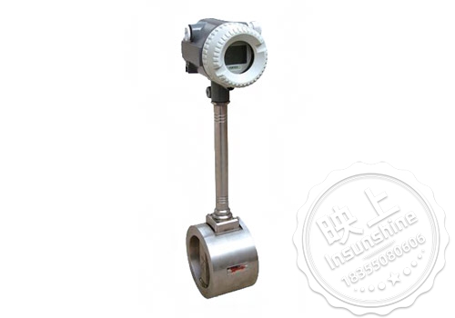
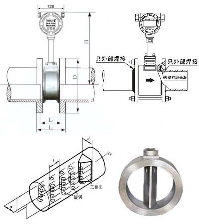
CH-LU vortex flowmeter is mainly used for industrial pipeline media fluid flow measurement, such as gas, liquid, steam and other media. It is characterized by small pressure loss, large range, high accuracy, in the measurement of the volume of flow conditions almost independent of the fluid density, pressure, temperature, viscosity and other parameters. There are no moving mechanical parts, so high reliability and low maintenance. Instrument parameters can be stabilized for a long time. Vortex flowmeter using piezoelectric stress sensor, high reliability, can be in -20 ℃ ~ +250 ℃ working temperature range. There are analog standard signals, but also digital pulse signal output, easy to use with computers and other digital systems, is a more advanced, ideal flow meter.
Second, the technical parameters
1、Measuring medium: gas, liquid, vapor;
2, the caliber specifications of the French card-mounted caliber selection 25,32,50,80,100;
3, flange connection type caliber selection 100,150,200;
4、Flow measurement range Normal measurement of the flow rate range Reynolds number 1.5 × 10⁴ ~ 4 × 10⁶; gas 5 ~ 50m / s; liquid 0.5 ~ 7m / s;
5、Measurement accuracy 1.0 grade 1.5 grade;
6, the measured medium temperature: room temperature -25 ℃ ~ 100 ℃; 7. High temperature -25 ℃ ~ 150 ℃ -25 ℃ ~ 250 ℃;
7. Output signal Pulse voltage output signal High level 8~10V Low level 0.7~1.3V;
8, pulse duty cycle of about 50%, transmission distance of 100m;
9、Pulse current remote signal 4~20 mA, the transmission distance is 1000m;
10、Meter use environment Temperature:-25℃~+55℃ Humidity:5~90% RH50℃;
11、Material Stainless steel, aluminum alloy;
12、Power supply DC24V or lithium battery 3.6V;
|
a thoroughfare (DN) |
Liquid flow range (m3/h) |
Output frequency range (Hz) |
Gas flow range (m3/h) |
Output frequency range (Hz) |
|
15 |
1.2~6.2 |
90~900 |
5~25 |
265~2640 |
|
20 |
1.5~10 |
40~396 |
8~50 |
218~1982 |
|
25 |
1.6~16 |
32~325 |
10~70 |
172~1420 |
|
32 |
2~20 |
20~250 |
15~150 |
130~1350 |
|
40 |
2.5~25 |
13~130 |
22~220 |
115~1147 |
|
50 |
3.5~35 |
9~93 |
36~320 |
96~854 |
|
65 |
6~60 |
8~82 |
50~480 |
61~583 |
|
80 |
10~100 |
6~65 |
70~640 |
45~417 |
|
100 |
15~150 |
5~50 |
130~1100 |
43~367 |
|
125 |
25~250 |
5~47 |
200~1700 |
33~290 |
|
150 |
40~400 |
4~40 |
280~2240 |
27~221 |
|
200 |
80~800 |
3~33 |
580~4960 |
24~207 |
|
250 |
140~1400 |
3~26 |
970~8000 |
20~171 |
|
300 |
200~2000 |
2~22 |
1380~11000 |
17~136 |
External Dimensions
|
a thoroughfare (DN) |
L (mm) |
H (mm) |
|
|||||||||
|
10 |
66 |
360 |
||||||||||
|
15 |
66 |
360 |
||||||||||
|
20 |
66 |
360 |
||||||||||
|
25 |
66 |
360 |
||||||||||
|
32 |
66 |
365 |
||||||||||
|
40 |
80 |
370 |
||||||||||
|
50 |
80 |
375 |
||||||||||
|
65 |
93 |
383 |
||||||||||
|
80 |
100 |
390 |
||||||||||
|
100 |
125 |
400 |
||||||||||
|
125 |
145 |
470 |
||||||||||
|
150 |
165 |
500 |
||||||||||
|
200 |
196 |
580 |
||||||||||
|
250 |
235 |
650 |
||||||||||
|
300 |
255 |
700 |
||||||||||
|
Installation Diagram |
||||||||||||
|
caveat |
legend (of a map, etc) |
|||||||||||
|
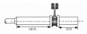
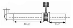
1、Expand the installation of the pipe
For small diameter and large flow, must expand the installation of the pipe, while ensuring that the flow meter before the straight section ≥ 15D, after the straight section ≥ 5D
|
|
|||||||||||
|
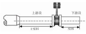
2、Shrinking pipe installation
For large caliber small flow, must be reduced installation, while ensuring that the flowmeter before the straight section ≥ 15D, after the straight section ≥ 5D
|
|
|||||||||||
|
3、The installation of elbow
If the front end of the flowmeter has 90 ° elbow or T-type connector, to ensure that the flowmeter before the straight section ≥ 15D, after the straight section ≥ 5D
|
|
|||||||||||
|
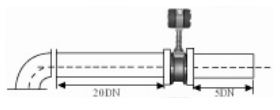
4, the same plane two elbow installation
If the front of the flowmeter has two 90 ° elbow, to ensure that the flowmeter before the straight section ≥ 20D, after the straight section ≥ 5D
|
|
|||||||||||
|
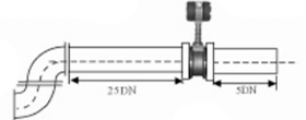
5, the installation of two elbows in different planes
If the front of the flowmeter has two 90 ° elbow, to ensure that the flowmeter before the straight section ≥ 25D, after the straight section ≥ 5D
|
|
|||||||||||
|
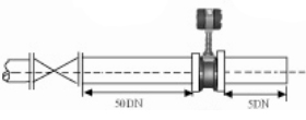
6、Installation of adjustment valve
If the flowmeter before and after the need to install control valves, to ensure that the flowmeter before the straight section ≥ 25D, after the straight section ≥ 5D
|
|
|||||||||||
|
lProduct Selection Chart |
||||||||||||
|
CH-LU |
Vortex flowmeter |
|||||||||||
|
caliber (mm) |
10 |
DN10~DN50 (Flange, Clamp, Threaded, Clamped) |
||||||||||
|
50 |
DN50~DN150 (Clamping type, flange type) |
|||||||||||
|
100 |
DN100~DN300(Flange Type, Clamping Type) |
|||||||||||
|
300 |
DN300Above is the insertion type |
|||||||||||
|
Installation |
B |
push-pull |
||||||||||
|
L |
Flange connection type |
|||||||||||
|
C |
inserted |
|||||||||||
|
Mode of compensation |
/ |
uncompensated |
||||||||||
|
BC |
Temperature and pressure compensation |
|||||||||||
|
W |
Single Temperature Compensation |
|||||||||||
|
Y |
Single pressure compensation |
|||||||||||
|
Measuring medium |
Y |
fluids |
||||||||||
|
Q |
gas (i.e. gaseous substance) |
|||||||||||
|
Z |
vapor |
|||||||||||
|
temperature range |
T1 |
Normal temperature type (below 120°C) |
||||||||||
|
T2 |
High temperature type (below 250°C) |
|||||||||||
|
pressure rating |
P1 |
Normal pressure~1.6MPa |
||||||||||
|
P2 |
2.5MPa |
|||||||||||
|
P3 |
4.0MPa |
|||||||||||
|
Body Material |
A |
carbon steel |
||||||||||
|
B |
304 stainless steel |
|||||||||||
|
C |
316 stainless steel |
|||||||||||
|
Power supply method |
D |
two-wire systemDC24V 4~20mA |
||||||||||
|
H |
two-wire systemDC24V 4~20mA+HART协议 |
|||||||||||
|
C |
battery powered |
|||||||||||
|
Additional Options |
R |
RS485 MODBUScommunication protocols |
||||||||||
|
M |
pulse output |
|||||||||||
|
B |
Explosion-proof (ExII CT6) |
|||||||||||